
In this article i will give the basic steps to build a 4 channels Ethernet relay that can be used as a network power switch for many purposes. the importance of this project resides in having the ability to control those relay “wirelessly” from your smart phone through WiFi or even from outside your house through the internet.
That relay board is a LAN based, you need to attach it to your network through a network cable. i.e. you will need a WiFi Access point with at least one Ethernet port.
Below is the final assembled project:
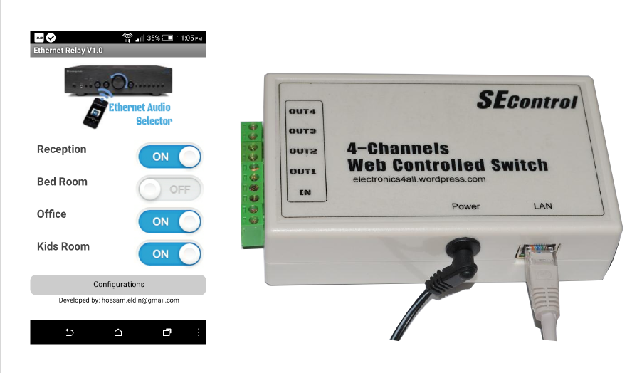


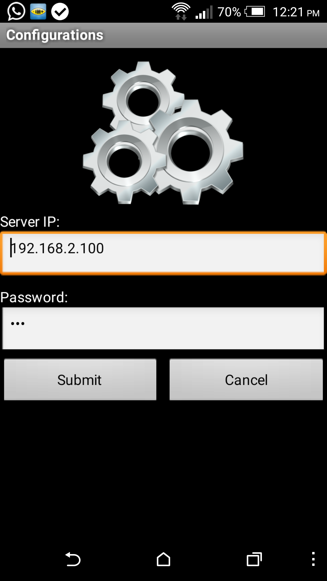
The software image on the left is for the Android application that i built to controls the 4 Relays. Of course you can build the application you want, any application that can send HTTP requests can be used with this project, i will describe this later in this article.
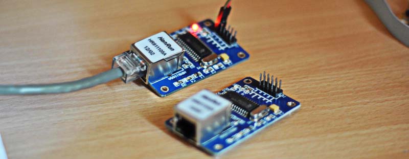
The Ethernet Module:
The project has two main “hearts”, the ATMEL Atmega328P as the brain, and the Ethernet module ENC28J60 which saved lots and lots of work, otherwise you will have to build the TCP/IP stack in your microcontroller code. believe me it’s not an easy task. This module communicates with the microcontroller through SPI, typically, 6 pins is only required to work with this little thing.
The Microcontroller:
One of the challenges that i had in this project is to find a good library for the ENC28J60 Ethernet module. initially i started with the PIC microcontrollers, although that are very efficient but i found that writing a native C to handle the communication with the Ethernet module is a time consuming task which can be easily solved by using Arduino based microcontroller like Atmega328P which is the heart of Arduino Uno board. the idea is to use the Arduino libraries built for that module which give you the ability to build a “tiny” web server to receive and analyse the HTTP requests, then accordingly send orders to the relays through the output ports.
You will need to have at least one Arduino Uno board, write the code and save it to the microcontroller then pull it and insert it into your circuit.
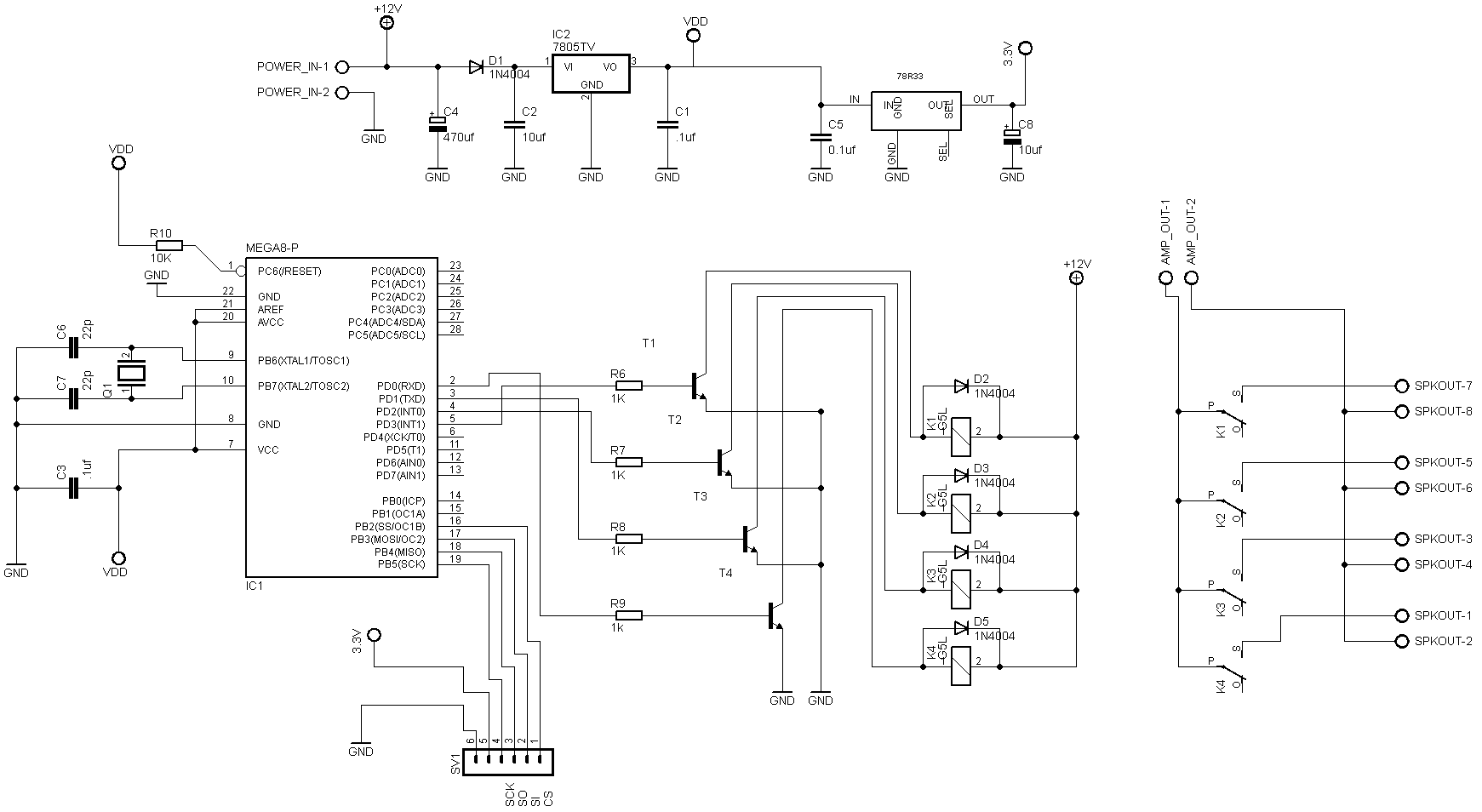
Circuit Diagram
I used the famous CadSoft Eagle to build the PCB and circuit diagram, please contact me if you want the Eagle files.
PCB Artwork

Arduino Code
Make sure that both ETHER_28J60 and etherShield libraries are included in your Arduino project
I will add them later to this post
Note that the code was configured to have a fixed IP 192.168.2.100, you need to change it before compiling the project to have the same network address of you network.
You can invoke this small webserver directly from the browser, ex: http://192.168.2.100?d1=on to turn ON the first relay and http://192.168.2.100?d1=off to turn it off. Invoking the server with the status parameters will send the realys’ ex: http://192.168.2.100?status will print the following:
d1=ond2=offd3=ond4=on
you will need to parse those values in your program and change the layout accordingly.
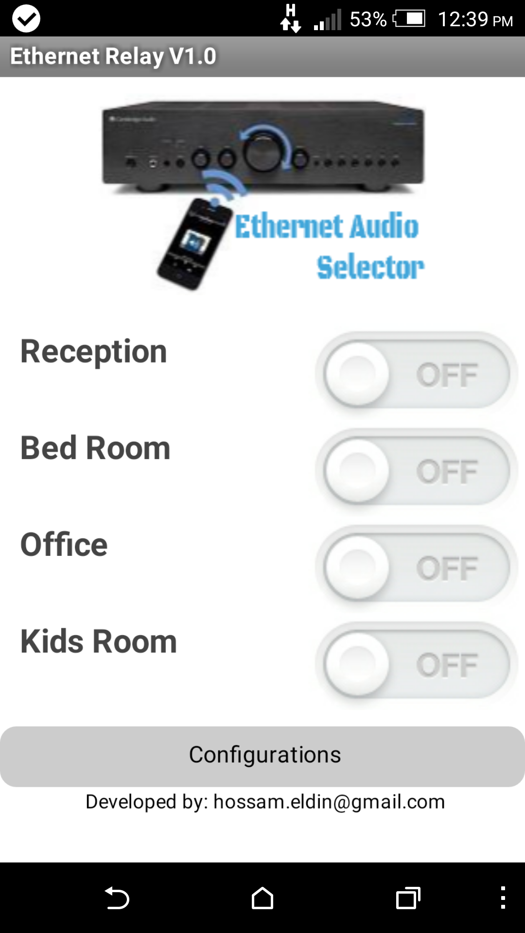
I have built an Android application to control this device. It was built using MIT App Inventor, the application was built as a sound system controller for my house, below is a screenshot of that App.
App Inventor source will be uploaded soon …
 |
 |
// A simple web server to turn 5 LED on or off
#include <Arduino.h>
#include "etherShield.h"
#include "ETHER_28J60.h"
#include <EEPROM.h>

int outPin0 = 0; // relay1 to pin 4
int outPin1 = 1; // relay2 to pin 3
int outPin2 = 2; // relay3 to pin 2
int outPin3 = 3; // relay4 to pin 1
int outPin4 = 4; // relay5 to pin 0

const int ledPin = 9; // led status pin 9

byte value0;
byte value1;
byte value2;
byte value3;
byte value4;

//int ledState = LOW;
//long previousMillis = 0;
//long interval = 1000;


static uint8_t mac[6] = {
 0x54, 0x55, 0x58, 0x10, 0x12, 0x24}; // this just needs to be unique for your network,

static uint8_t ip[4] = {192, 168, 2, 100}; // IP address for the webserver
static uint16_t port = 80; // Use port 80 - the standard for HTTP
String myip="";

ETHER_28J60 e;

void current_status() {
 int val = 0;

 val = digitalRead(outPin0);
 if (val == LOW)
 e.print("d1=off");
 else
 e.print("d1=on");

 val = digitalRead(outPin1);
 if (val == LOW)
 e.print("d2=off");
 else
 e.print("d2=on");


 val = digitalRead(outPin2);
 if (val == LOW)
 e.print("d3=off");
 else
 e.print("d3=on");


 val = digitalRead(outPin3);
 if (val == LOW)
 e.print("d4=off");
 else
 e.print("d4=on");
}


void LoadLastSettings() {
 value0 = EEPROM.read(0x00);
 value1 = EEPROM.read(0x01);
 value2 = EEPROM.read(0x02);
 value3 = EEPROM.read(0x03);
 value4 = EEPROM.read(0x04);

 if (value0==0)
 {
 digitalWrite(outPin0, LOW);
 }
 else if (value0==1)
 {
 digitalWrite(outPin0, HIGH);
 }


 if (value1==0)
 {
 digitalWrite(outPin1, LOW);
 }
 else if (value1==1)
 {
 digitalWrite(outPin1, HIGH);
 }


 if (value2==0)
 {
 digitalWrite(outPin2, LOW);
 }
 else if (value2==1)
 {
 digitalWrite(outPin2, HIGH);
 }


 if (value3==0)
 {
 digitalWrite(outPin3, LOW);
 }
 else if (value3==1)
 {
 digitalWrite(outPin3, HIGH);
 }


 if (value4==0)
 {
 digitalWrite(outPin4, LOW);
 }
 else if (value4==1)
 {
 digitalWrite(outPin4, HIGH);
 }
}//End


void setup()
{
 e.setup(mac, ip, port);

 pinMode(outPin0, OUTPUT);
 pinMode(outPin1, OUTPUT);
 pinMode(outPin2, OUTPUT);
 pinMode(outPin3, OUTPUT);
 pinMode(outPin4, OUTPUT);
 pinMode(ledPin, OUTPUT);


 LoadLastSettings();


} // End Setup


void loop()
{
 char* params;
 if (params = e.serviceRequest())
 {

 if (strcmp(params, "?status") == 0)
 {
 current_status();
 }

// to be implemented
// else if (strcmp(params, "?ipchange") == 0) { // ?ipchange192.168.1.250
// myip = substr(params,9,3);
// }


 e.print("<h1>Ethernet Relay Control<h1>");
 e.print("<h2><a href='/?d1=off'>Relay1OFF</a></h2>");
 e.print("<h2><a href='/?d1=on'>Relay1ON</a></h2>");
 e.print("<h2><a href='/?d2=off'>Relay2OFF</a></h2>");
 e.print("<h2><a href='/?d2=on'>Relay2ON</a></h2>");
 e.print("<h2><a href='/?d3=off'>Relay3OFF</a></h2>");
 e.print("<h2><a href='/?d3=on'>Relay3ON</a></h2>");
 e.print("<h2><a href='/?d4=off'>Relay4OFF</a></h2>");
 e.print("<h2><a href='/?d4=on'>Relay4ON</a></h2>");
 e.print("<h2><a href='/?d5=off'>out5off</a></h2>");
 e.print("<h2><a href='/?d5=on'>out5on</a></h2>");

 if (strcmp(params, "?d1=on") == 0)
 {
 value0=1;
 digitalWrite(outPin0, HIGH);
 e.print("<h1>d1=on</h1>");
 }
 else if (strcmp(params, "?d1=off") == 0)
 {
 value0=0;
 digitalWrite(outPin0, LOW);
 e.print("<h1>d1=off</h1>");
 }

 if (strcmp(params, "?d2=on") == 0)
 {
 value1=1;
 digitalWrite(outPin1, HIGH);
 e.print("<h1>d2=on</h1>");
 }
 else if (strcmp(params, "?d2=off") == 0)
 {
 value1=0;
 digitalWrite(outPin1, LOW);
 e.print("<h1>d2=off</h1>");
 }


 if (strcmp(params, "?d3=on") == 0)
 {
 value2=1;
 digitalWrite(outPin2, HIGH);
 e.print("<h1>d3=on</h1>");
 }
 else if (strcmp(params, "?d3=off") == 0)
 {
 value2=0;
 digitalWrite(outPin2, LOW);
 e.print("<h1>d3=off</h1>");
 }
 if (strcmp(params, "?d4=on") == 0)
 {
 value3=1;
 digitalWrite(outPin3, HIGH);
 e.print("<h1>d4=on</h1>");
 }
 else if (strcmp(params, "?d4=off") == 0)
 {
 value3=0;
 digitalWrite(outPin3, LOW);
 e.print("<h1>d4=off</h1>");
 }
 if (strcmp(params, "?d5=on") == 0)
 {
 value4=1;
 digitalWrite(outPin4, HIGH);
 e.print("<h1>d5=on</h1>");
 }
 else if (strcmp(params, "?d5=off") == 0)
 {
 value4=0;
 digitalWrite(outPin4, LOW);
 e.print("<h1>d5=off</h1>");
 }
 e.respond();

 EEPROM.write(0x00, value0);
 EEPROM.write(0x01, value1);
 EEPROM.write(0x02, value2);
 EEPROM.write(0x03, value3);
 EEPROM.write(0x04, value4);

 }
}
Testing the project

Nice, but if i understood right, this works only as long as your mobile connected to the same network, what if i want to control it via Internet from different network, how to make public server ?
LikeLike
Hi Kareem, if you want to access the device from outside your network, I.e. through Internet, then you need to configure your router and add a port mapping it’s also preferred to have a static ip (about 15L.E/month). Or use no-ip.com.
Let me know if you need more clarification
LikeLike
I am new to the Arduino.
I find the escutcheon bookstore chain.
Maybe if I want to sati and thousand from library and source app that I want to change my little app as needed.
Thank you.
Gold Project congratulations.
LikeLike
I am new to the Arduino
sketch_apr27a.ino:3:25: fatal error: etherShield.h: No such file or directory
please help me..
LikeLike
You need to download the Ethernet library as i mentioned
LikeLike
Hi Hosameldin! Can you send for me the aia file of your project. My email hai.intercon@gmail.com
Thank for your help!
LikeLike
Hi Hai, will upload it here soon
LikeLike
Good…~~
please send me aia file…~~
baesj89@yahoo.co.kr
Thanks…Have a Good Day…~~
LikeLike
I don’t know if I’m being stupid but I can’t find what you used as T1-T4 on the diagram.
LikeLike
Hi Thanasis,
T1 to T4 is a generic NPN transistor, 2N2222A will do the job
Thanks
Hossam
LikeLike
Hi,
I need Eagle files, please reply back.
My email id is 3rockyfighter@gmail.com.
Thanks
LikeLike
Excellent project
Could you send me android code (aia,apk)? please
msadik.sen@hotmail.com
Thanks…Have a nice day
LikeLike
can i upload this to arduino uno
LikeLike
Excellent project
Android .aia , app inventor
Thanks
LikeLike
gilberto-goncalves@outlook.com.br
LikeLike
thanks
LikeLike
.aia app inventor
gilberto-goncalves@outlook.com.br
LikeLike
Hi great job !
could you send me the the android code?
Thanks
Paolo
LikeLike
Could you send me android code (aia,apk)? please
cpiyawat@hotmail.com
Thanks…Have a nice day
LikeLike
Nice boss send me (aia,apk)? please
badshazec@gmail.com
Thanks…Have a nice day
LikeLike
Please send me the Eagle files.
My email is nttungitg@gmail.com.
Thanks!
LikeLike